DE10-Nano: HPS and FPGA interaction - Part 2 - FreeRTOS LED Blinky
Introduction
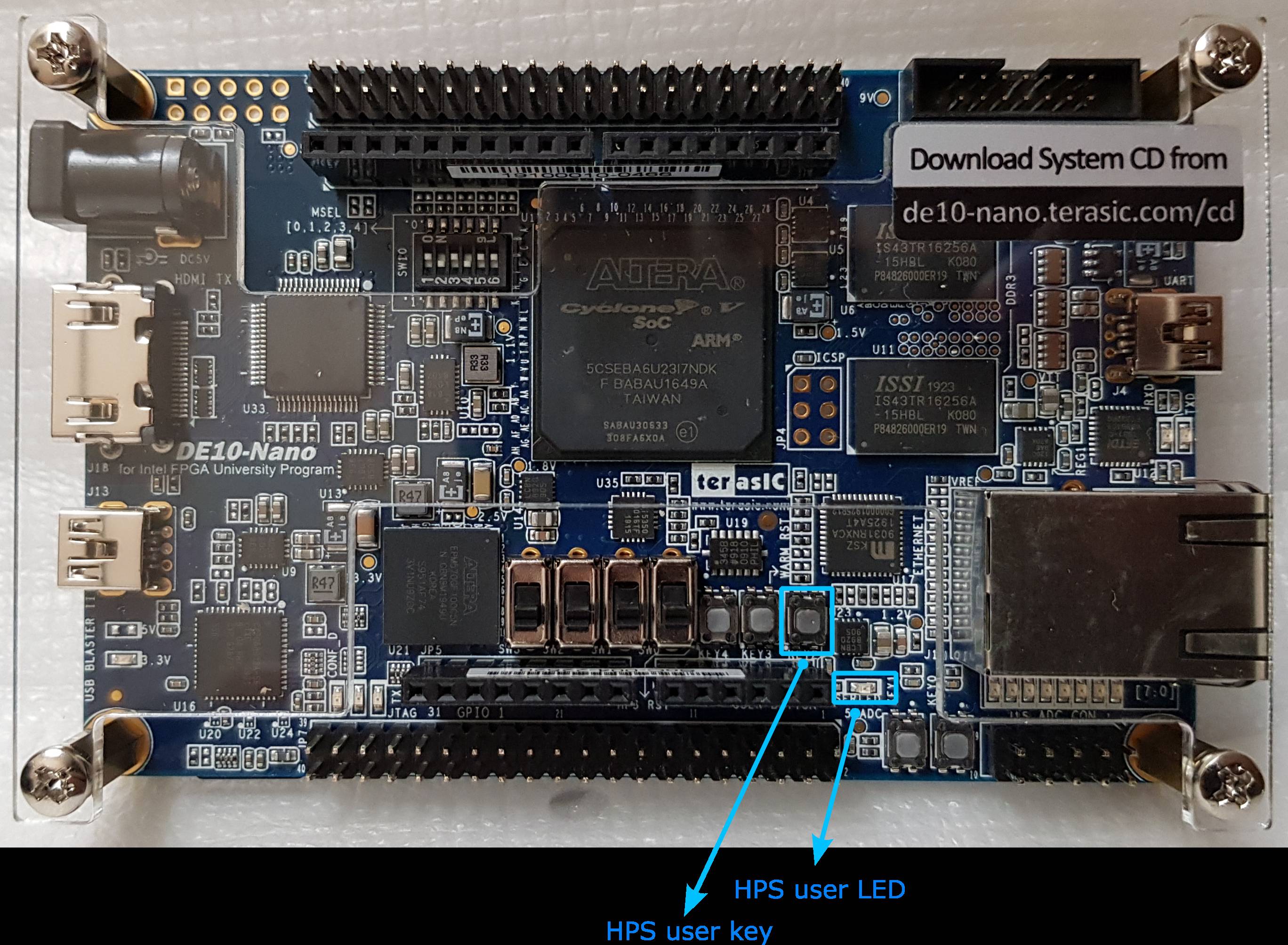
In part 2 we will look at using the single HPS input key and LED.
On the DE10-Nano board these are highlighted in blue. They are wired to the HPS GPIO pins and we can control them with the GPIO controller built into the HPS. Everything is on the processing side so there is no interaction with the FPGA in this case.
FreeRTOS Blinky
To demonstrate the input key and LED control, I've decided to use FreeRTOS (Kernel), a preemptive multitasking library, which is a good use case for implementing the key capture and blinking a LED when the processor has to do everything.
This program creates some tasks that runs preemptively to blink an LED and also read an input key. Both are wired to the processing side and labelled as HPS_KEY and HPS_LED within the DE10-Nano user manual.
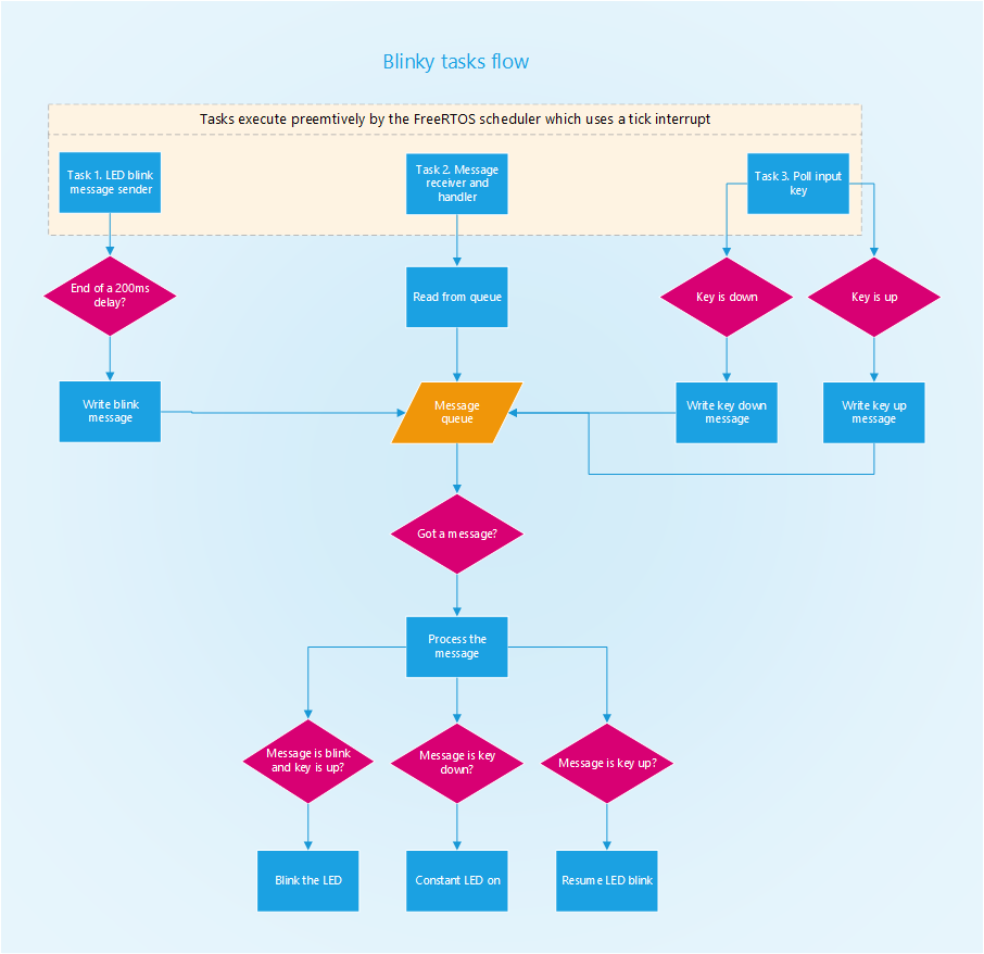
The program starts with the LED blinking, holding the input key stops the blinking but keeps the LED on, releasing the key resumes the blinking. You can download it from my github de10nano_freertos_blinky.
Boot flow
I don't have time to write a detailed description for this example, but this may help some people - a diagram illustrating the FreeRTOS blinky application startup boot flow (note, for simplicity some steps may be omitted or simplified):
This second diagram illustrates the flow of each tasks for input key poll mode (note, for simplicity some steps may be omitted or simplified):
Appendix
| Acronym | Description |
|---|---|
| HPS | Hard Processor System. In the system block diagram, HPS is the block portion representing the computer system (SoC). |
| HPS GPIO | HPS General Peripheral Input Output. This is a hardware I/O controller integrated inside the HPS. |
Document date: Rev 1: 15 Feb 2024


